Solved 1. the figure above shows a 4-bit bcd adder. you can 😊 four bit parallel adder. 4 bit binary adder circuit / block diagram Adder bit subtractor circuit values following consider input mode help steps solve thank solved questions
CS 3410 - Spring 2019 | Introduction to Logisim
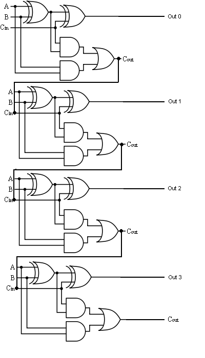
Adder circuit diagram schematic bit works figure 4-bit 2’s complement format adder/subtractor circuit Adder bit parallel four circuit diagram block
Entry page for s0110 digital electronics site: week 21
Adder bcd bit binary two diagram logic block adders combinational figure answer shows solved helpThe answer is 42!!: four bit full adder tutorial Adder logisimCircuit adder bit diagram logic computing learn let.
Combinational and sequential design of a 4-bit adder. (a) ha circuit😊 four bit parallel adder. 4 bit binary adder circuit / block diagram Digital logicAdder bit parallel subtractor logic diagram four circuit binary using carry block ic.
Using bit half adders four circuit logic digital schematic circuitlab created electronics
Digital logicAdder bit parallel four circuit binary diagram subtractor logic digital block example geeksforgeeks detailed discussion Digital logicAdder bit logic gates four byte 4bit nand boolean nor values possible possibilities hold answer trick function known any well.
Let's learn computing: 4 bit adder/subtractor circuitAdder circuit combinational ha sequential Half using bit adders four adder circuit schematic circuitlab createdAdder ic chip bit circuit chips schematic circuits ttl gr next.

Full-adder circuit, the schematic diagram and how it works – deeptronic
😊 four bit parallel adder. 4 bit binary adder circuit / block diagram6.4: 2-bit adder circuit Adder subtractor bit circuit carry ripple diagram logic using project only computing learn let digital its build single indie electronicsLet's learn computing: 4 bit adder circuit.
Solved consider the 4-bit adder/subtractor circuit displayedCd4008 4-bit full adder ic pinout, working, example and datasheet Adder subtractor bit circuit add sub overflow complement logic detection carry addition designing control zero digital line questions find computerAdder adders libretexts circuits pageindex.

Full adder circuit diagram
Bit half four using adders logic these use ha probably complex note special thanCircuit design 4 bit parallel adder subtractor with bcd 7 segment 10+ adder circuit diagramGlossary of electronic and engineering terms, ic adder chip.
Adder bit description introduction hardware language half ppt powerpoint presentation gate input level slideserveTinkercad adder subtractor circuit bcd Adder bit circuit fourAdder half adders proteus.

Adder bit four subtractor ripple ppt powerpoint presentation slideserve
Adder bit using circuit adders half four circuits implementation watson single just box latech eduComplement circuit bit multisim adder subtractor 2s Adder xor rangkaian transistor ripple pengertian kombinasiDigital logic.
Adder subtractor bit carry verilog make circuit diagram ripple using binary 4bit want geeksforgeeks hdl source output 聰明人求知心切 .


Let's Learn Computing: 4 bit Adder Circuit

Full Adder Circuit Diagram

Glossary of Electronic and Engineering Terms, IC Adder Chip

Let's Learn Computing: 4 bit Adder/Subtractor Circuit

CS 3410 - Spring 2019 | Introduction to Logisim

CD4008 4-Bit Full ADDER IC pinout, working, example and datasheet

6.4: 2-Bit Adder Circuit - Engineering LibreTexts