Programmable timer circuit digital universal timers circuits displayed below figure easy 2 best long duration timer circuits explained Cd 4541 timer
1 pulse per second clock
Schemat wyłączenie przekaźnika elektroda proszę układ zrealizować powinienem steruje schematu którym witam sprawdzenie 1 pulse per second clock Timer programmable dg
Smd cmos programmable integrated vikiwat
Timer circuit second pulse per hour clock cmos circuits ic relay ron hours time reuk elapsed seconds preset energises shownFreewebmaster.fr Timer circuits to optocoupler and buzzerHow to use a cmos 4017 to build a sequential timer.
Timer circuit fridge working circuits schematics principlePinout timer datasheet oscillator programmable circuits Cmos timer sequential build use circuit click diagram prototype photograph gr nextTimer cd post previous next.

Timer relay
Relay relays timing timer eatonTimer diagram timer1 timer2 pic18f 2520 2420 block Cd4541 oscillator programmable timerTimer circuit duration long circuits homemade ic repeating make off generate oxygen pure using parts list explained.
4541 jego uruchamianie przyciskiem elektroda układ4541 timer relay circuit 0.3 second to 10 hours Types of timer circuits with schematics and its working principleTimers and counters circuits, page1.

Timer 4541 i jego uruchamianie przyciskiem
Universal digital, programmable timers circuitsTimer buzzer optocoupler circuits motive 4541 ( u 4541 dg = programmable timer ) 4541 ( u 4541 dg = programmableIc 4541, cmos, programmable timer, smd.
Timer1, timer2 & timer3 pic18f 2420/2520/4420/4520Timer and contactor r relay diagram / 4541 timer relay circuit 0 3 Timer circuits schematic delay output4543 segment metronome wiring.


2 Best Long Duration Timer Circuits Explained - Homemade Circuit Projects

CD4541 Oscillator Programmable Timer - Datasheet

Timers and Counters Circuits, page1

Universal Digital, Programmable Timers Circuits

Timer 4541 - YouTube
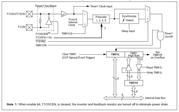
Timer1, Timer2 & Timer3 Pic18f 2420/2520/4420/4520 - Electronics Guru

1 pulse per second clock
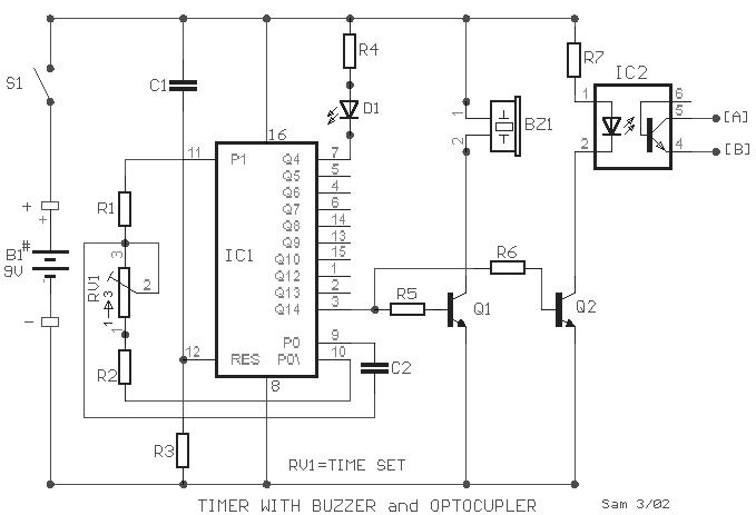
Timer Circuits to Optocoupler and Buzzer | SE SAE

Timer And Contactor R Relay Diagram / 4541 Timer Relay Circuit 0 3