[solved] design a 4-bit "universal shift register" using four Shift register bit left right circuit logic simple logisim calculator using display click size Register bit
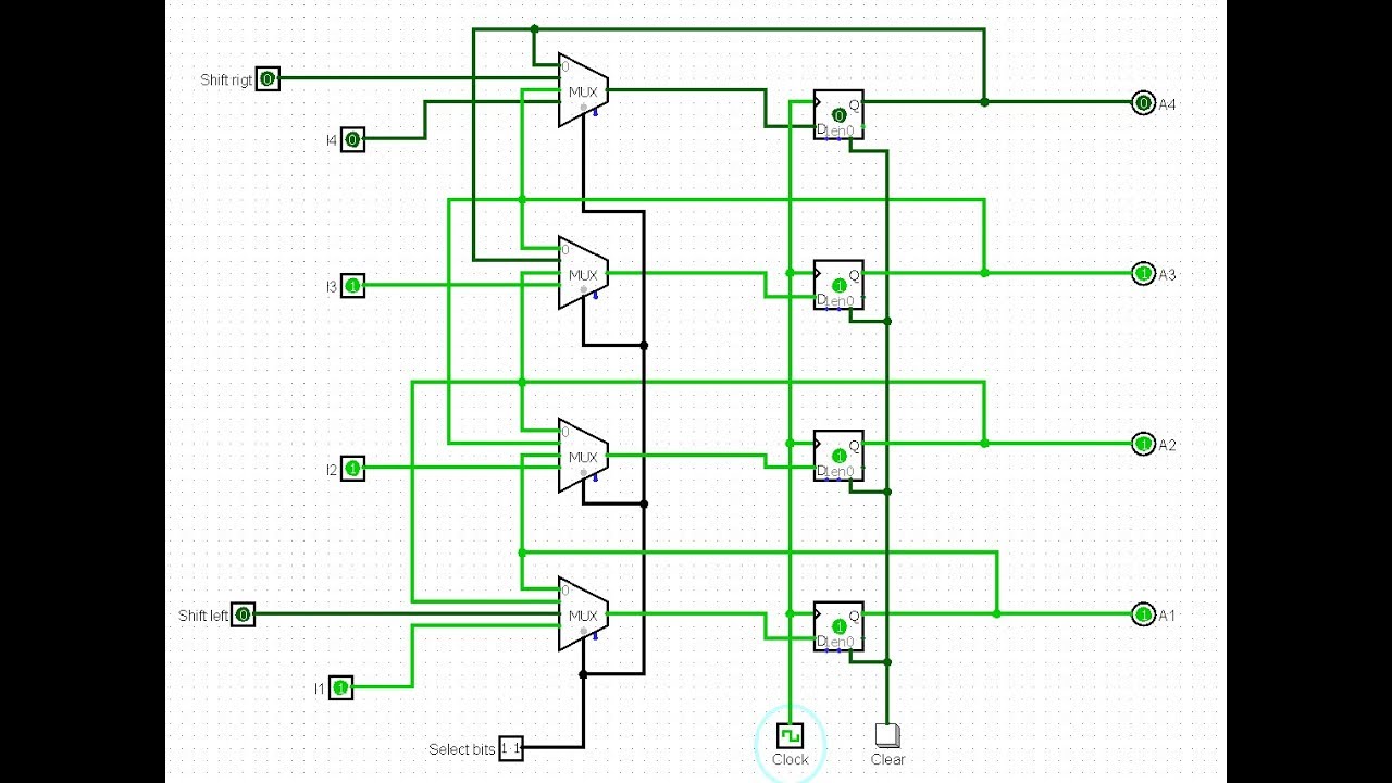
Fig.1: 4 Bit universal shift register
Block diagram of 4-bit pipo shift register using d flip flop Mux multiplexers flip flops q3 outputs transcriptions described Bit memory parallel serial circuit register logisim question clock
Shift register universal bit verilog code coding fig
Shift register bit usingSolved design a circuit that uses two 4-bit universal shift For this assignment, you must create a circuit using logism thatShift flop pipo.
4 bit register file in logisimSolved cms transistor layout of a 4-bit register Register logisim bit fileUsing implements bit storing capable schematics.

4 bit shift register using 74194
Digital logicRegister shift circuit serial parallel bit logic registers digital memory clock logisim flipflop flip flop right piso electronics example question 4-bit shift registerRegister bit layout transistor circuit sram using cmos task solved nmos pmos schematic.
Register shift bit four parallel load flip control using flops two inputs there solved answer has problem gates explain transcribedElectronics blog: fpga vhdl four bit register with load hold Register bit using shift numbers stack schematic adding circuit circuitlab created registers loadSolved design a four-bit shift register with parallel load.
Register bit shift logisim universal
Register parallel registersRegister shift bit circuit parallel circuits flip electronic flops integrated inputs build ic made power Pass sequencer circuit otherwiseThe circuit below is a 4-bit register with parallel.
Register shift ic bit chip circuit schematic circuits gr nextBit circuit register shift adder subtractor adders reg lab shifter Register bit shift parallel output input serial load figure shown circuit data solved 1011 waveform questions convert used serially digitalGlossary of electronic and engineering terms, ic shift register chip.

Register bit load hold vhdl four circuit fpga behavioural testbench approach comparison test code
Register bit circuit clear parallel load transcribed hasn answered question yet text been show asynchronousFig.1: 4 bit universal shift register Circuit analysisRegister shift bit.
4 bit shift registerCs201 design adders lab Bit circuit using alu logism circuits memory meets investigate utilize following should different then store used assignment must create4 bit universal shift register in logisim.

[solved] how to make circuit using logism that implements a memory
Solved question 2 a 4-bit shift register shown in figureMy blog: simple calculator display logic circuit (made using logisim) Multisim register bit shift.
.
![[Solved] How to make circuit using Logism that implements a memory](https://i2.wp.com/www.coursehero.com/qa/attachment/12960644/)
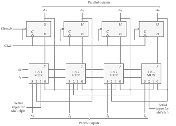
Fig.1: 4 Bit universal shift register

clock - 4-bit memory serial to parallel memory register circuit
My Blog: Simple calculator display logic circuit (made using logisim)

Solved Design a four-bit shift register with parallel load | Chegg.com

CD4014 - An 8-bit Shift Register With Parallel Inputs

The circuit below is a 4-bit register with parallel | Chegg.com

For this assignment, you must create a circuit using Logism that