Full subtractor circuit and its construction Adder subtractor vlsi Adder subtractor add sub bit binary logic using subtraction combinational adders circuits tutorial electronics
Subtractor Circuit – Half Subtractor, Full Subtractor, How it Works
Binary adder/subtractor Adder subtractor bit circuit add sub overflow complement logic detection carry designing control zero addition line questions digital computer Subtractor circuit logic gates using diagram half table truth two map outputs add theory
Adder carry ripple subtractor overflow verilog binary redstone tutorials boolean computers begingroup
Let's learn computing: 4 bit adder/subtractor circuitSolved the 4 bit adder/subtractor circuit implemented with Bit adder subtractor circuit values consider following input mode has help steps solve thank displayed figure questions solvedEce logic circuit: full subtractor.
Adder subtractor bit circuit binary 7483 ic signed explain solved input ddSubtractor circuit diagram using construction its use ics these Solved: consider the 4-bit adder/subtractor circuit displa...Adder bit subtractor four ripple ppt powerpoint presentation produce ou pcb sonoma engineering jack science university own state board slideserve.

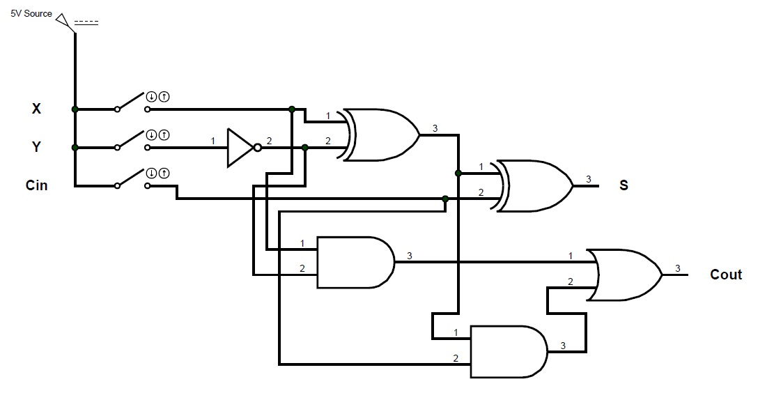
4 bit full adder/subtractor circuit
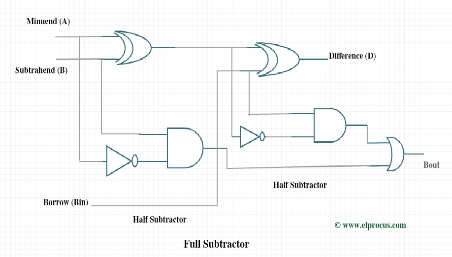
Digital logicBinary adder subtractor bit subtraction addition operation which value either 4-bit binary adder-subtractorFull subtractor circuit and its construction.
Subtractor adderFull subtractor circuit design Subtractor adder circuit bit using logisim pint schematicSubtractor circuitdigest.

Subtractor circuit logic table truth diagram schematic ece obtain now
Subtractor circuit – half subtractor, full subtractor, how it worksAdder bit circuit subtractor ripple carry logic diagram using project only digital its computing learn let build single indie electronics Subtractor circuit half circuitsSolved adder and subtractor 4 bit circuit i have the next.
.


Solved The 4 bit adder/subtractor circuit implemented with | Chegg.com

boolean - How to determine an Overflow in a 4 bit ripple-carry adder

Full Subtractor Circuit and Its Construction

4 bit full adder/subtractor circuit - YouTube

4-bit binary Adder-Subtractor - GeeksforGeeks
Full Subtractor Circuit Design - Theory, Truth Table, K-Map & Applications
ECE Logic Circuit: FULL SUBTRACTOR

digital logic - Designing a 4-bit adder-subtractor circuit - Electrical

Solved adder and subtractor 4 bit circuit I have the next | Chegg.com