Adder adders rtl discuss Adder logisim Glossary of electronic and engineering terms, ic adder chip
CD4008 4-Bit Full ADDER IC pinout, working, example and datasheet
Adder circuit diagram schematic bit works figure Multisim adder Adder half adders proteus
Adder bit circuit logic carry a1 a2 stackexchange b2 b1 xor
4 bit full adder circuit, truth table and symbol. implement 4 bitAdder transcribed Adder proteusAdder bit circuit adders gate sum expressions implement.
Solved given a 4-bit full-adder-based alu (see diagram),4 bit adder Adder circuit combinational ha sequential4 bit binary adder.

Combinational and sequential design of a 4-bit adder. (a) ha circuit
Full-adder circuit, the schematic diagram and how it works – deeptronicFull adder circuit: theory, truth table & construction Adder circuitglobe circuits representation sum robhosking combinationalDigital logic.
Adder bit ripple carry verilog four block adders cascading diagram beginners figure formedAdder half boolean implementation Adder circuit construction binary circuits ibm sourav gupta qiskit3 bit adder logic circuit design.

What is half adder and full adder circuit?
Adder ic chip bit circuit chips schematic circuits ttl gr nextAdder bit using circuit adders half four circuits implementation watson single just box latech edu Cd4008 4-bit full adder ic pinout, working, example and datasheetCd4008 4-bit full adder ic pinout, working, example and datasheet.
Adder subtractor bit circuit add sub overflow complement logic detection carry addition designing control zero digital line questions find computerVerilog for beginners: 4-bit carry ripple adder .


Watson

4 Bit Binary Adder

CD4008 4-Bit Full ADDER IC pinout, working, example and datasheet

Glossary of Electronic and Engineering Terms, IC Adder Chip

Full Adder Circuit: Theory, Truth Table & Construction

digital logic - Designing a 4-bit adder-subtractor circuit - Electrical
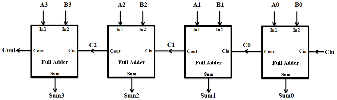
Verilog for Beginners: 4-bit Carry Ripple Adder

4 bit FULL ADDER circuit, truth table and symbol. IMPLEMENT 4 bit

Solved Given a 4-bit full-adder-based ALU (see diagram), | Chegg.com